
2026 Best Aviation Component Robotic Peening Cell?
Choosing the 2026 Best Aviation Component Robotic Peening Cell requires more than comparing robot reach or cycle time. The cell must deliver repeatable surface coverage across parts with different curves, edges, and fixture positions. A turbine blade, for example, may need a different path and media flow from a broad structural panel. Small setup errors matter.
A reliable evaluation looks at the complete process. Check robotic repeatability, nozzle control, media consistency, dust extraction, part fixturing, and inspection records. Ask how the system verifies coverage and flags process drift. Request evidence from representative components, not only an ideal demonstration. A polished video is not process validation.
“Repeatable coverage depends on controlling the whole process, not just the robot path.” This is an illustrative quotation from a fictional composite specialist, not a statement by a real named expert. For publication, replace it with a verified quotation from an identified aviation peening professional. That distinction matters. Buyers should also examine maintenance access, operator training, and data traceability. A cell can be technically capable yet difficult to sustain on a busy production floor. The best Aviation Component Robotic Peening Cell is therefore the one that meets documented component requirements and produces consistent, reviewable results in real operating conditions. Ask for trial data, inspect the setup, and confirm that the proposed process suits your parts. One caveat: supplier claims alone are not enough.
What Is a Robotic Peening Cell for Aviation Components?
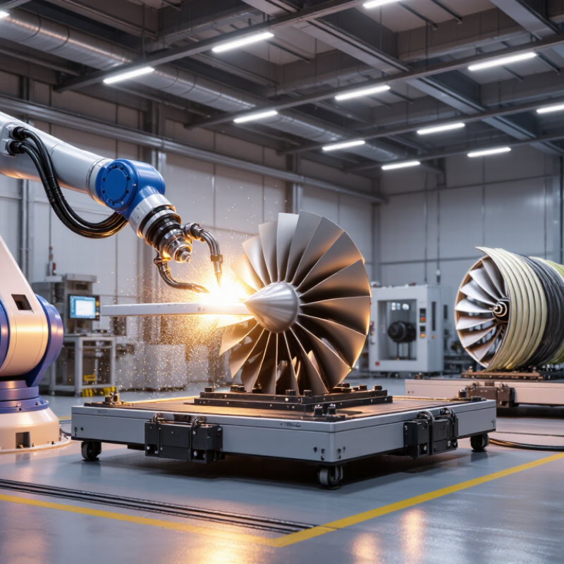
A robotic peening cell is an enclosed, programmable workspace that directs controlled impacts onto an aviation component’s surface. In shot peening, small media strike the metal and create compressive residual stresses that can help resist fatigue cracking. Think of a turbine disk or landing-gear part rotating beneath a carefully positioned nozzle. The robot follows a programmed path. That repeatability matters. A complete cell may include part fixtures, media recovery, dust extraction, and process monitoring. Operators still need to verify coverage and peening intensity using approved procedures and test methods.
The International Federation of Robotics’ World Robotics 2024 report recorded 541,302 industrial robots installed worldwide in 2023, with 4,281,585 in operation. Those figures show broad industrial adoption, not aviation peening performance specifically. In a peening cell, engineers must validate robot paths, nozzle distance, media flow, and exposure time for each component geometry. Small changes can leave shadowed areas or over-peen a surface. It is not a set-and-forget process. Fixtures can also restrict access to complex curves, and a programmed path may need adjustment after inspection. That practical limitation is easy to underestimate.
2026 Best Aviation Component Robotic Peening Cell? — What Is a Robotic Peening Cell for Aviation Components?
| Selection Dimension | What the Cell Does or Provides | What to Verify for an Aviation Application |
|---|---|---|
| Definition | An enclosed automated system that uses a programmed robot to direct shot-peening media at specified areas of a component. The cell typically combines robotic motion, media delivery, part handling, guarding, and process monitoring. | Confirm that the cell can reproduce the approved process for the actual component, rather than relying on robot automation alone as evidence of process compliance. |
| Purpose of shot peening | Shot peening plastically deforms a component’s surface and can create a layer of compressive residual stress. It is used on selected parts to support fatigue performance when required by the engineering specification. | Use only where specified by the design authority or approved process documentation. Peening is not a substitute for material, heat-treatment, or inspection requirements. |
| Typical system elements | Industrial robot, peening nozzle or wheel system, media storage and delivery equipment, dust collection, enclosure, workholding, controls, and process-monitoring instruments. | Check equipment compatibility, maintenance access, media-handling arrangements, containment, and the ability to monitor the process variables required by the applicable specification. |
| Robot and work envelope | The robot moves the nozzle or peening head along programmed paths. Cell layout and tooling determine which component surfaces can be reached and at what orientations. | Assess the largest and smallest parts, nozzle access, line of sight, collision risks, fixture access, and repeatable positioning. Reach and payload should be selected from the part and tooling requirements. |
| Peening media | Media type, size, condition, and delivery method are selected for the approved process. Metallic shot is common in aerospace shot peening; other media may be specified for particular applications. | Verify media identification, permitted size and condition, segregation, screening or classification controls, and traceability requirements. Do not interchange media without process approval. |
| Intensity and process parameters | Peening intensity is established and verified using the method and test media required by the governing process specification. Other controlled parameters may include media flow, air pressure, nozzle distance, angle, and traverse speed. | Use approved parameter limits and verification procedures. Values are application-specific; there is no single intensity or setting that is suitable for all aviation components. |
| Coverage and robot path | Programmed paths control how the peening stream traverses the target surface. Coverage requirements define the treatment of the specified area and are established by the applicable engineering or process documentation. | Validate coverage on representative geometry, including edges, transitions, recesses, and other hard-to-reach areas. Confirm repeatability after program, fixture, or equipment changes. |
| Masking and workholding | Fixtures position the part consistently; masks or protective covers shield surfaces that must not be peened. Their design depends on the component geometry and process instructions. | Check fixture repeatability, part protection, mask durability, access for loading and unloading, and controls that prevent incorrect orientation or incomplete masking. |
| Process monitoring and records | Controls may record recipe selection, robot program, alarms, and measured process data. The required level of monitoring and record retention depends on the customer and governing specification. | Define required records, calibration controls, access permissions, data review, and handling of out-of-limit conditions before production release. |
| Quality requirements | Aerospace peening requirements are controlled by the applicable drawing, customer or design-authority process specification, and relevant industry standards. SAE AMS2430 and AMS2432 are examples of shot-peening specifications; applicability depends on the contract and process. | Identify the exact revision and requirements that apply. The drawing and approved customer or design-authority documentation take precedence where specified; standards should not be assumed to apply automatically. |
| Containment and operator safety | An enclosed cell contains rebounding media and dust. Interlocked guarding, dust collection, noise control, and safe loading and maintenance provisions are typical design considerations. | Review the site risk assessment, applicable safety rules, dust-management requirements, interlocks, lockout procedures, and access for inspection and maintenance. |
| Choosing the “best” cell | The best-fit cell is the one that can reliably process the required component family while meeting approved process, quality, safety, and production needs. | Compare process qualification support, part and fixture range, verified coverage, monitoring and traceability, changeover needs, maintenance support, and integration with existing quality systems. |
Important: This table provides general selection guidance, not a process specification or approval. Final equipment design and operating parameters must be validated against the applicable component requirements and approved aerospace process documentation.
FAQS
It is an enclosed workspace where a robot directs controlled impacts onto a component’s surface. A turbine disk may rotate beneath a carefully positioned nozzle. The cell can include fixtures, media recovery, dust extraction, and process monitoring.
The impacts create compressive residual stress near the surface. This stress can help oppose forces that open small fatigue cracks during repeated loading. It is not a guarantee; results depend on the material, shape, and service loads.
A programmed robot can repeat paths around curved edges and recessed areas. This may improve consistency when the setup is properly validated. Repeatability matters. The robot still needs suitable programming and regular checks.
Media size, impact intensity, coverage, nozzle angle, and exposure time all affect treatment. Engineers also check media flow and nozzle distance. Small changes can leave shadowed areas or over-peen a surface.
They can use test coupons, surface checks, and component-level inspection. Approved intensity strips and calibration records can help confirm the process. Settings alone are not proof.
Not always. Fixtures may block access, and complex internal passages can be difficult to treat and inspect. A programmed path may need adjustment after inspection. That limitation deserves more attention.
Review path repeatability, process controls, guarding, dust collection, and maintenance access. Check whether fixtures hold parts securely without masking important surfaces. A polished demonstration may not reveal awkward loading or difficult cleaning.
Records should link component identification with process settings and inspection results. Sensors and alarms can flag pressure drops or interrupted flow, but they cannot replace inspection. Some automation claims need a closer look.
Conclusion
An Aviation Component Robotic Peening Cell uses programmable robots to apply controlled peening treatments to aircraft components with consistent coverage and repeatable process settings. By introducing beneficial compressive stresses at the surface, robotic peening can help components resist fatigue cracking and extend service life when the process is properly designed and validated. Suitable applications may include selected structural parts, landing-gear components, and other metal parts whose materials and geometry are compatible with peening.
Choosing a high-performing cell in 2026 means evaluating robotic accuracy, process control, coverage monitoring, flexibility, and integration with production workflows. Quality management should include documented parameters, inspections, and regular verification that the process meets engineering requirements. Effective safety systems, operator training, preventive maintenance, and timely replacement of worn equipment also help maintain reliable operation. The best solution is therefore one that combines repeatable treatment, clear quality records, safe operation, and practical long-term support.